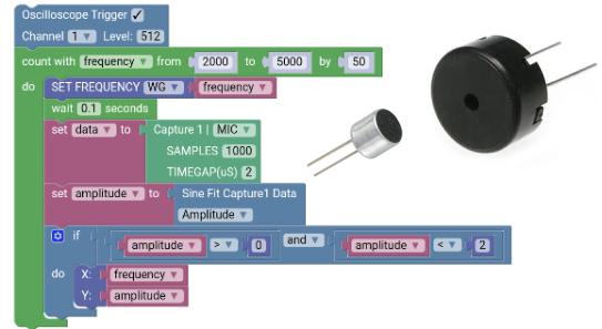
The drag and drop coding interface makes it easy to develop workflows to control real world events. It includes blocks to perform data acquisition, analysis , and visualization in addition to standard coding operators.
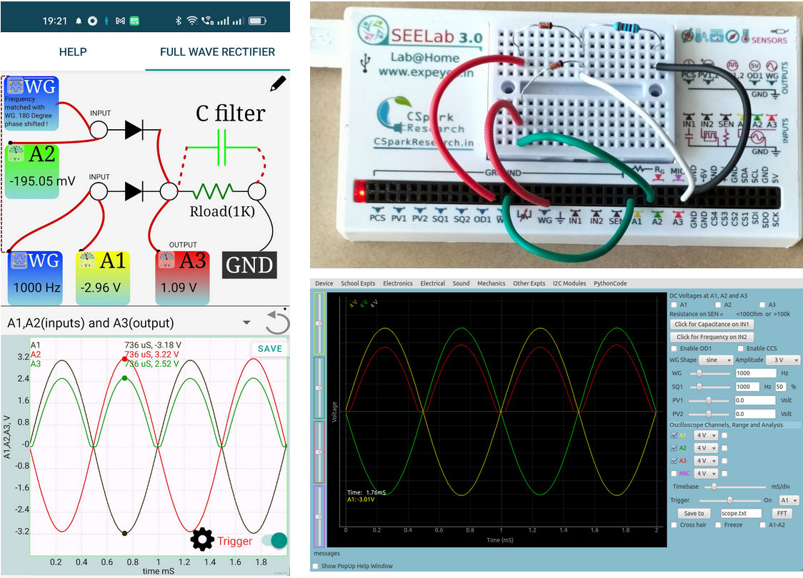
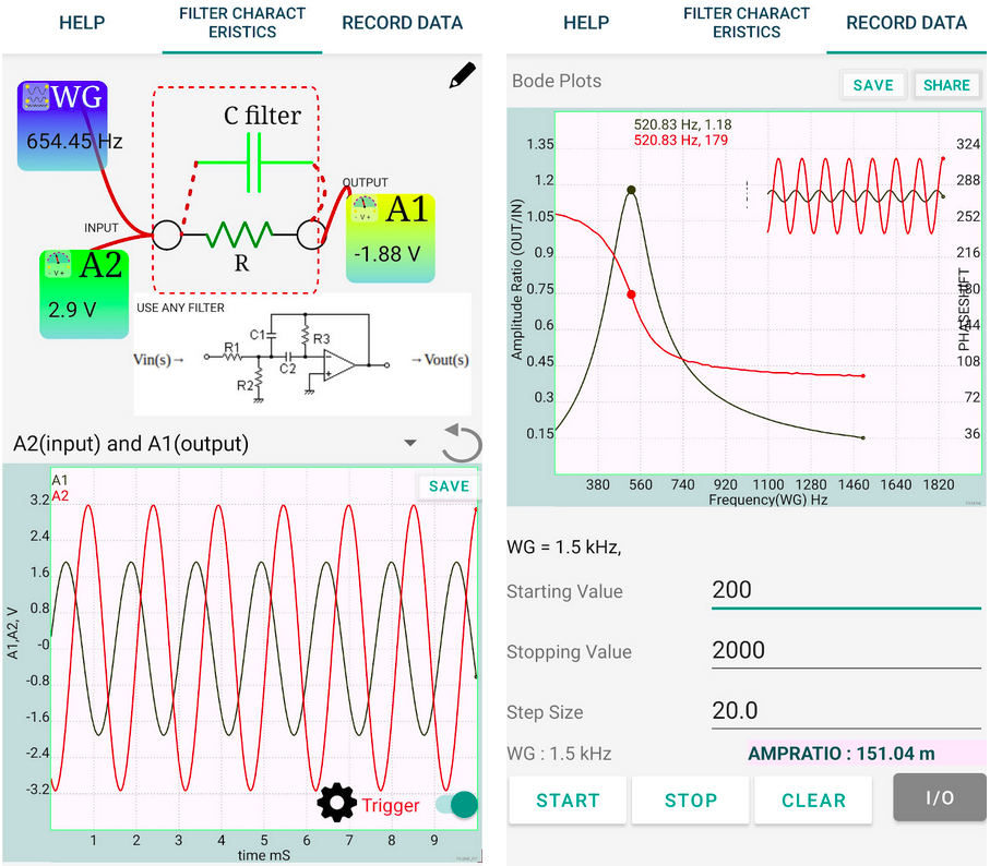
50+ code examples for experiments. from plotting sine waves, sine fitting, and LCR steady state response
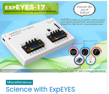
Youngsters can get started with simple experiments such as making lemon cells, parallel plate capacitors, dynamos. Excellent for demonstrating STEM principles.
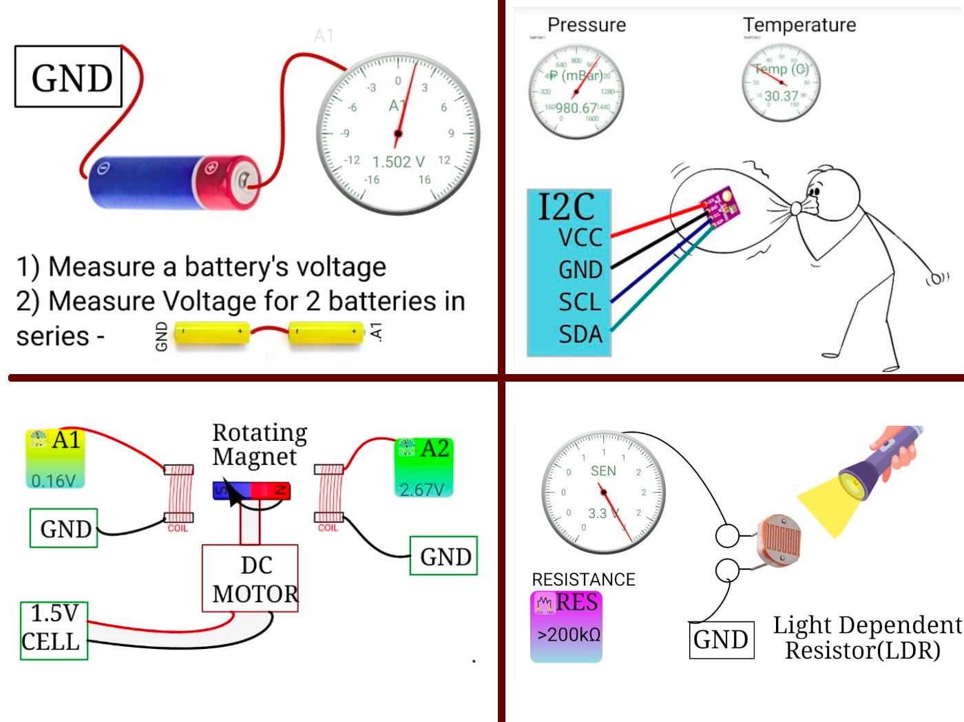
With this unique combination of tools tailor made for science education, a vast range of experiments are possible
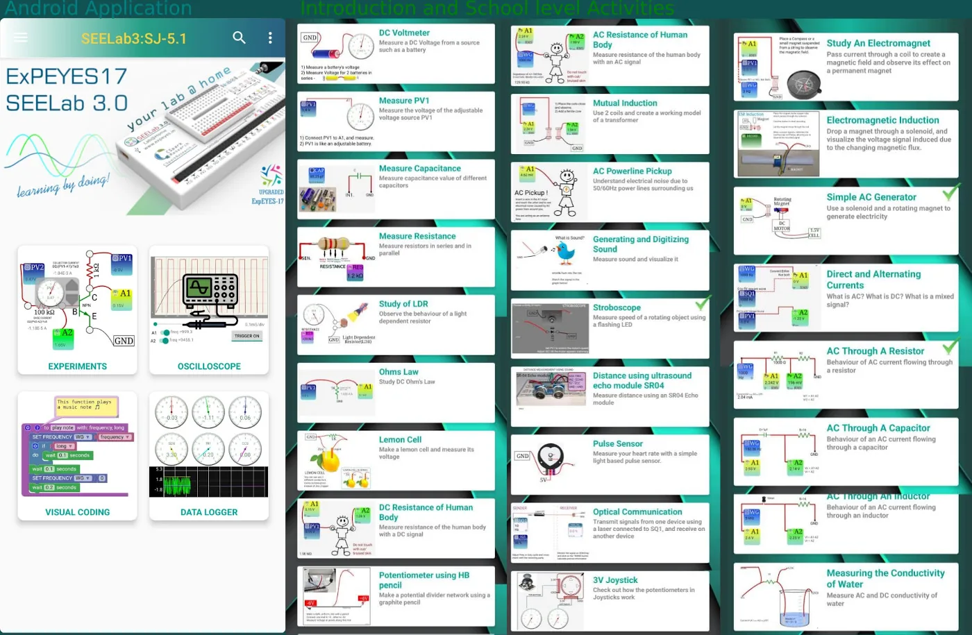
School Level science, electronics, electrical, mechanics, electrochemistry, acoustics...
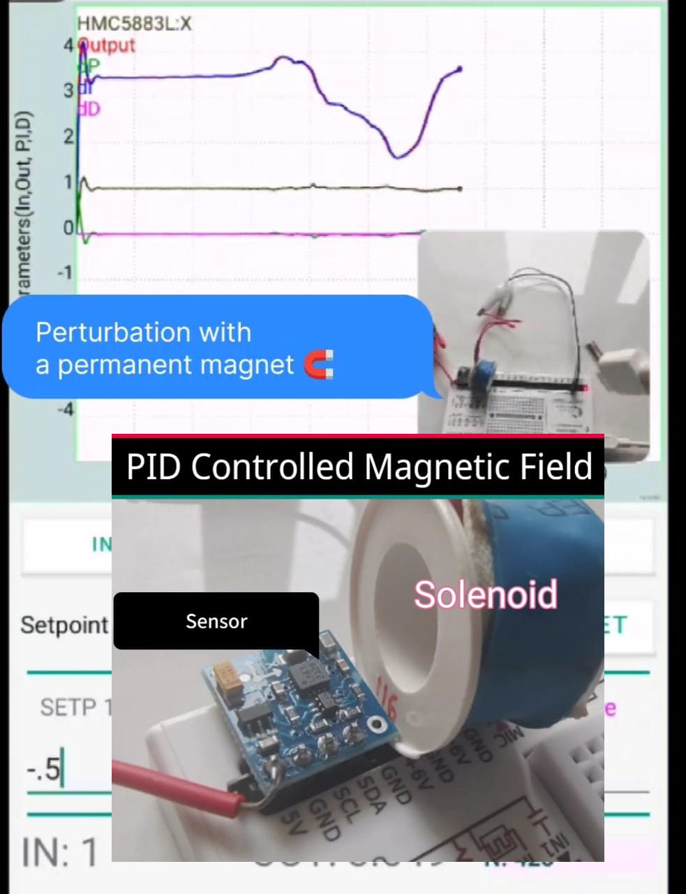
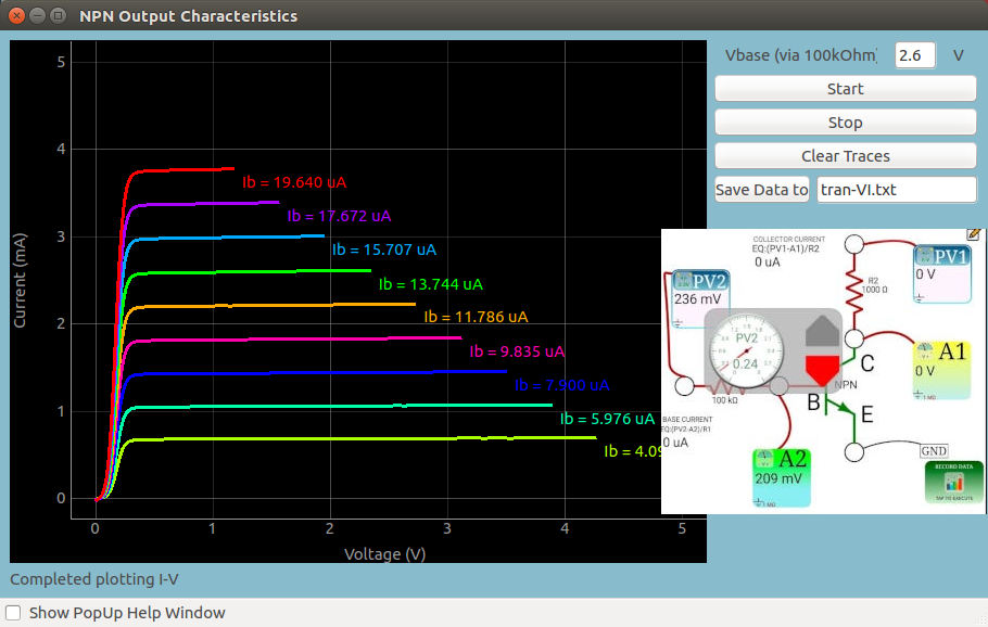
Choose any input and any output! Temperature controllers, magnetic field stabilizers, drone stability principles...
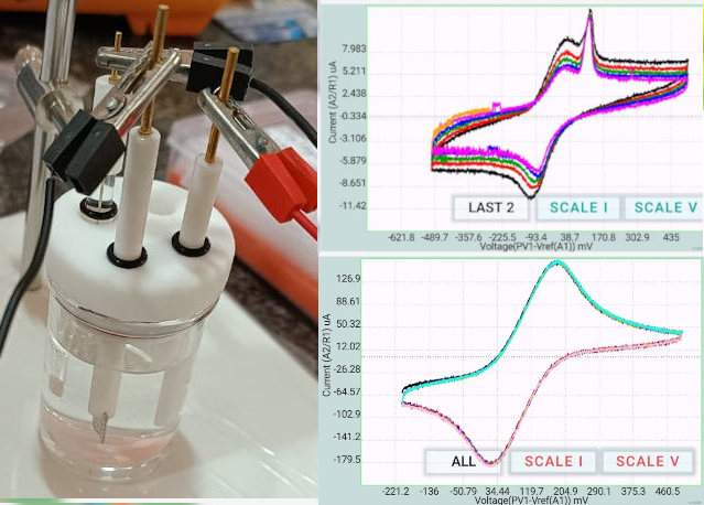
Wire up a 3 opamp circuit, and use SEELab'3 voltmeters and DACs to explore redox electrochemistry. Shown traces are for FeCN6+KCl , and an Ionic liquid. A simple CV experiment with a 1K resistor is also built-in
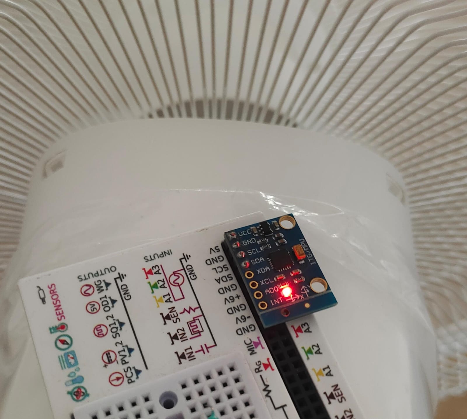
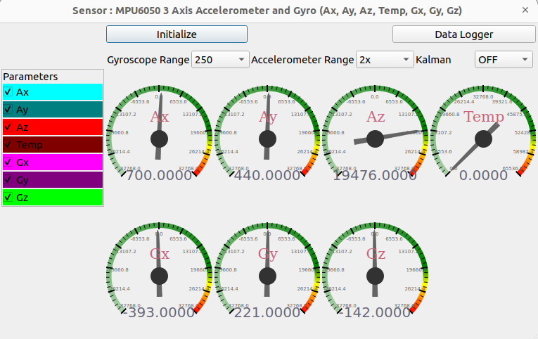
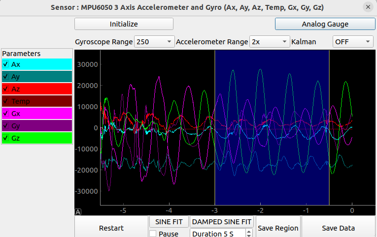
The sensor oscilloscope gets precise time correlated data from sensors. Used to study vibrational modes of mechanical oscillators. The speed of this BLDC fan was calculated from the FFT of data from an accelerometer
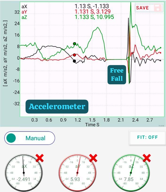
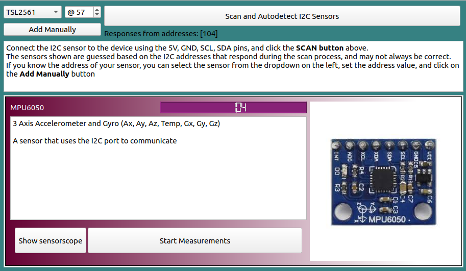
Record data from your phone's sensors! Accelerometer, gyro, magnetometer, luminosity... Plot/Analyse raw data. measure sub-millisecond time gaps between noises with the interactive acoustic stopwatch
Check out MOOC courses on Moodle. Tailored for different audiences
Scischool.inCourse material developed by Dr. Ajith Kumar For Scischool.in
Open source python library lets you integrate it into complex setups
from expeyes import eyes17
p=eyes17.open()
p.set_pv1(1) # +1 Volt output on PV1
v = p.get_voltage('A1') #Read voltages from A1 input
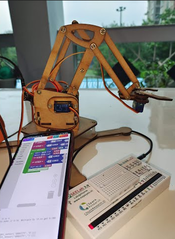
This 4-DOF affordable robotic arm can be controlled via your phone using the visual coding interface. SEELab3 controls the servos via a PCA9685 servo controller, and responds to hand gestures detected with AI.


| Title | Journal | Author(s) |
|---|---|---|
|
Study of magnet fall through conducting pipes using a data logger |
Springer: SN Applied Sciences | Abdul Kareem Thottoli et al. |
|
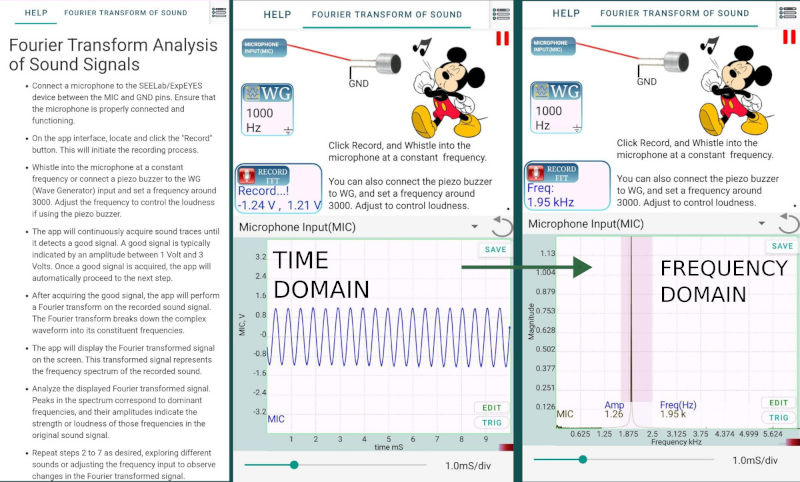
Study of Fourier series of user defined waveforms using ExpEYES−17 kit |
IOP Science Physics Education | Subhrajyoti Biswas |
|
Design and development of an implantable circuit for adjusting required pressure inside of respiratory system |
Springer Nature: Microsystem technologies Volume 31, pages 367–380, (2025) | Moupali Roy, Soumyendu Bhattacharjee |
|
Innovative Approach for the Study of Tuning Circuit with Open Source Tools |
IOP Science ECS Transactions DOI 10.1149/10701.1497ecst | Shubha S, Rajesh BM, Avadhani DN and Madhura T K |
|
Determination of the band gap of germanium and silicon using ExpEYES-17 kit |
IOP Science Physics Education | Subhrajyoti Biswas |
|
Construction and remote demonstration of an inexpensive but efficient experimental setup for studying self-inductance and mutual-inductance between two coils |
IOP Science Physics Education 10.1088/1361-6552/ad22f3 | Arijit Roy, Munmun Ghosal, Abhishek Mallick |
|
The radiation-induced characteristic shift on control-semiconductors used in linac head |
25th international conference on medical physics - innovations in radiation technology and medical physics | Shyamprasad et al. |
|
Study of Fourier series of user defined waveforms using ExpEYES−17 kit |
Phys. Educ. 57 035008 | Subhrajyoti Biswas |
|
Study of magnet fall through conducting pipes using a data logger |
SN Applied Sciences(https://doi.org/10.1007/s42452-019-1086-z) | Abdul Kareem Thottoli et al. |
|
Construction and remote demonstration of an inexpensive but efficient linear differential variable transformer (LVDT) for physics or electronics teaching during COVID-19 pandemic |
IOP Science Physics Education, Volume 58, Number 1( 10.1088/1361-6552/ac93de) | Arijit Roy et al 2023 Phys. Educ. 58 015007 |
|
Microcontroller based study of diode thermometers for online demonstration of undergraduate laboratory classes in COVID-19 lockdown |
IOP Science Physics Education, Volume 57, Number 4 (10.1088/1361-6552/ac563f) | Subhrajyoti Biswas and Durjoy Roy 2022 |
|
ANALYSIS BY USING EXPEYES KIT TO DETERMINE THE VIBRATION MODES OF THE LIQUID |
ISSN (Online): 2455-3662 EPRA International Journal of Multidisciplinary Research (IJMR) | Komal Dani, Shreelekha Meherwade |