 Jithin B.P.


 Jithin B.P.
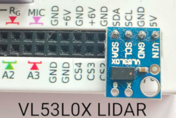
Plug the sensor to the I2C port by connecting 5V, GND , SCL, and SDA pins. Place a reflective object in front of this sensor such that the invisible laser pulse emitted from the sensor can bounce back towards the sensor. The object does not have to be a mirror. Any light coloured item will do, such as even a tennis ball.

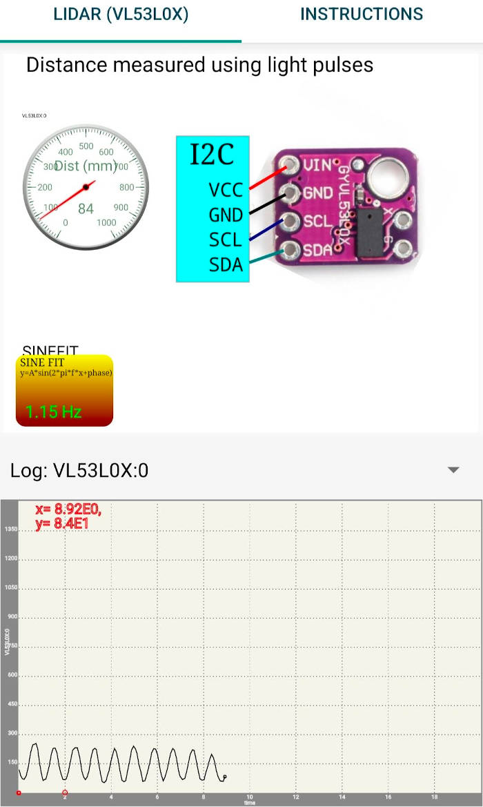
The screenshot below shows data with the sensor pointed at an oscillating object above it, and the oscillations are measured in millimeter units. T he X-Axis records time relative to the latest recorded point. This data can be analysed to extract frequency, amplitude, and damping coefficients of a mass spring system.

The SR04 uses sound pulses, and therefore requires a flat surface on the measurement surface facing it so that the reflected sound pulses are returned back to the sensor. This makes it difficult to use in traditional experiments such as pendulums with spherical bobs. The VL53L0X only needs an optically reflecting surface .
The videos below use the SR04 sound based ranging module, but which suffers from limitations such as not being able to reflect effectively from spherical surfaces . For most pendulums, the bob is spherical. The VL53L0X only needs the surface to be slightly reflective to light, and is a better alternative.
When a mass suspended on a spring is made to oscillate, the period of oscillation is given by T = 2 * pi * sqrt( m/k), where m is the mass and k is the spring constant. We can measure the period of oscillation by measuring the distance to the moving mass as a function of time. The distance versus time graph is fitted with a sine function to calculate the frequency. The photograph below shows a metal plate suspended on a spring and the SR04 facing it from the bottom. The distance to the oscillating plate is measured for 5 seconds and the data is fitted to a sine function.

A video of the experiment is HERE
The period of oscillations of a pendulum also can be measured using SR04 connected to ExpEYES. The figure shows a pendulum with a rectangular bob, but one can use a spherical bob with a piece of paper (to provide a flat reflecting surface) pasted to it. The measured frequency is 1.05 Hz for a pendulum having a length of 22cm. One can calculate the value of acceleration due to gravity from this data. Video
It is possible to measure the distance to a body falling under gravity. The value of ‘g’ can be calculated by fitting the data with the polynomial S(t)= a * t^2 + b * t + c ‘g’ is given by 2*a
Add the details of the sensor to the sensorConstants.java file. For the VL53L0X
	}else if(dev.equals("VL53L0X")){
		address = (byte) 0x29;
		count = 1;
		min = new double[] {0};
		max = new double[] {1000};
		channels = new String[] {"Dist (mm)"};
	}else if(dev.equals("TSL2561")){
		address = (byte) 0x39;
		count = 2;
The address is the I2C address. Count is the number of parameters. the min and max arrays are for each parameter. since this has only one, these have one element each. 0 to 1000 mm the channels array is for describing each parameter. Only one.
create a VL53L0X.java class in explib which implements sensorMethods.java sensorMethods has the following 3 functions
	String getDescription();
	List getData();
	double getDataPoint(int channel);
override all of them
getData is most important, and returns a list of values fetched from the sensor as per the sensorConstants order.
code
	public static HashMap<String,String> supportedSensors = new HashMap<String, String>(){{
		put("VL53L0X",VL53L0X.class.getCanonicalName());

		.
		.
		.
		.
	}};

	public static HashMap<String,String> sensorNames = new HashMap<String, String>(){{
		put("VL53L0X", "Lidar based distance measurement");
		.
		.

	}};
And we’re ready to go. Create a schematic in inkscape with the text ‘VL53L0X:0’ somewhere on it, and open this svg file with the app. Results at the top of this blog