A pictorial walkthrough of the KuttyPy Layout, CAD Render, Graphical Application design, and Coding Interface
July 01, 2019
 Jithin B.P.
 Jithin B.P.
The kuttyPy (/kʊtipʌɪ/) Microcontroller training utility allows real-time manipulation of the registers in microcontrollers via a connected computer containing its python library.
setReg and getReg function calls serve the purpose of a live debugging and monitoring utility, and combined with Python’s visualization and analytical utilities, this approach has immense pedagogical potential for beginners.
The kuttyPy hardware is an ATMEGA32 microcontroller development board developed by the ExpEYES project, and is currently supported by this software. It contains the kuttyPy firmware, but can also be used to run other programs via its bootloader.
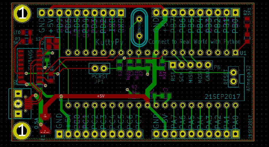
The kuttyPy hardware in itself is quite elementary. It has only the following components
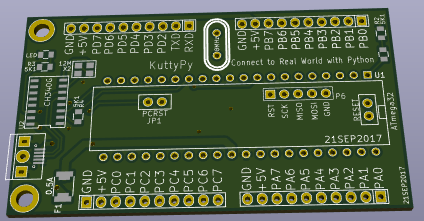
All of this was designed with KiCAD, an open-source EDA tool supported by CERN
KiCAD is incredibly powerful, allowing multi-layer board design with no space restrictions. It can also generate 3D CAD renders which can also be exported in common formats such as wrl and stp .
The KuttyPy is supposed to allow the user to control the microcontroller’s functions via a connected laptop, but without the hassle of compiling and uploading code. This is achieved with a code running on the kuttyPy which listens to incoming commands via the serial port, and changes pin states, reads ADCs, sets PWM values etc .
Originally, only a Python library was envisioned for the KuttyPy . However, with a powerful PyQt toolkit at our disposal, we decided to make a kid friendly graphical interface which resembled the hardware, but with buttons to directly toggle and read pins.
Furthermore, analog gauge widgets, and plots were added to enhance the usability. All thanks to the powerful free and open source python modules available such as PyQtgraph.
The source code has been uploaded on Github, and is also included in Debian sid.
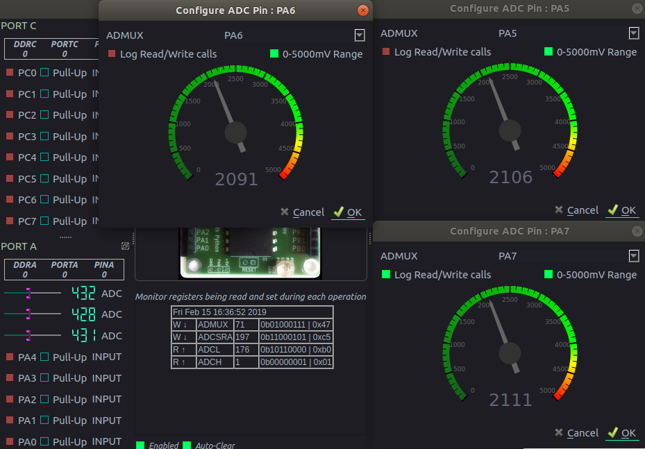
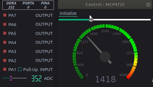
In addition to having 32 I/O pins at your disposal , you can also view the readings from 8 analog inputs in the form of fancy guages. In effect, it can act as an 8-channel, 10-bit, 0-5000mV voltmeter. Excellent for debugging your Arduino Projects!
The kuttyPy also supports I2C sensors such as MPU6050 , BMP180, TSL2561 in a plug and play format. The code has already been written for you.
Simply plug in the sensors to VCC,GND,SCL,SDA , click on scan, and select the sensor which is automatically detected.
Gauges and sliders magically appear and display the readings. Excellent utility for Physics students.
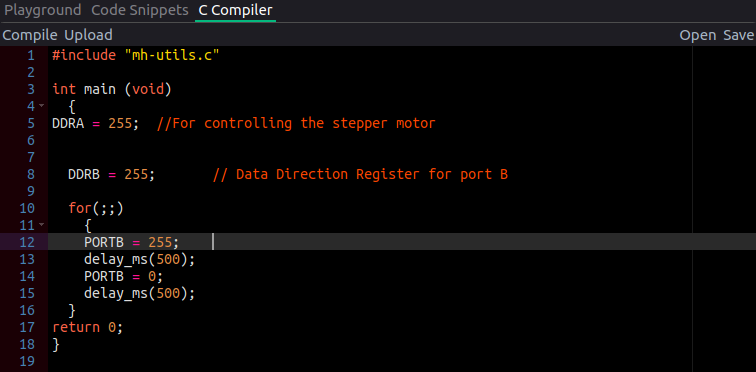
The standalone operation feature is not lost. The kuttyPy interpreter code is actually a part of the bootloader, so the users can compile C code with avr-gcc, and upload it to the kuttyPy. The user uploaded code will be frozen only when the KuttyPy graphical utility takes over for real time control of the pins. In all other scenarious, if a power supply of 5V is provided to the kuttyPy, it will execute the user uploaded code.
The graphical interface clearly shows the register operation associated with each click. For example, if PD0 was changed from input to output, and all other PD1-PD7 are inputs, the the log window will show
DDRD = 1 . 0b00000001 . 0x01
This is for students to grasp quickly, the idea of registers.
A fully equipped Python Library is also part of the package, and you can combine with other powerful modules such as Numpy, Matplotlib, and OpenCV to create automatation prototypes!
# Read ADC Values and plot them
import time
from kuttyPy import *
from matplotlib import pyplot as plt

setReg(ADMUX, (1<<6) | 5) #REF_AVCC | Channel 5
for a in range(50):
    setReg(ADCSRA, 196)
    cl = getReg(ADCL)
    ch = getReg(ADCH)
    plt.scatter(a, (ch<<8)|cl ,s=5)
    plt.pause(0.01) #Wait 10 mS