This experiment lets you study the output characteristics of PNP and NPN transistors in common emitter configuration. The dependence of saturation current on base current is studied
July 03, 2019
 Jithin B.P.
 Jithin B.P.
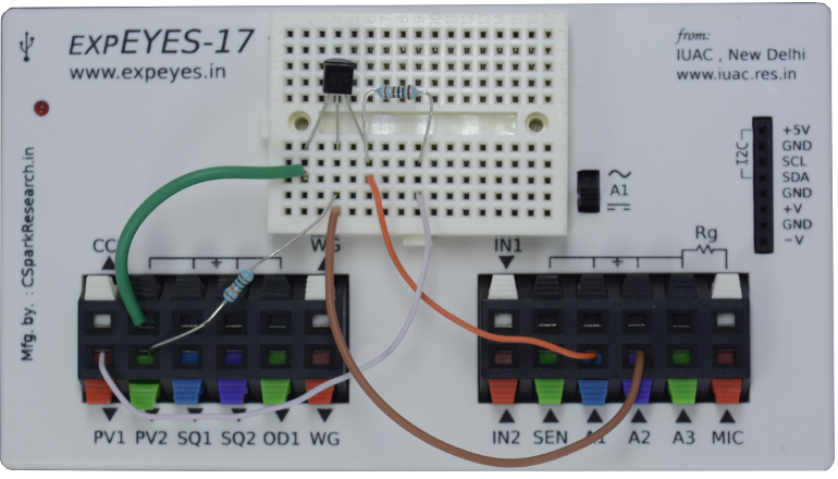
The schematic is wired as shown in the diagram below. The base current is set by the voltage from PV2, through a 100k resistor. The base voltage is measured to calculate the base current from Ib = (PV2-A2)/100K.
The collector voltage is monitored by A1. The collector is connected to PV1, through a 1k resistor.
For a selected base current, the voltage at PV1 is incremented in steps and at each step the collector voltage is measured. Corresponding collector current is calculated from i = (PV1-A1)/R. The transistor used is 2N2222, having a current gain of around 200.

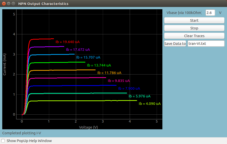
Screen shot of the output characteristics of an NPN Transistor in CE configuration
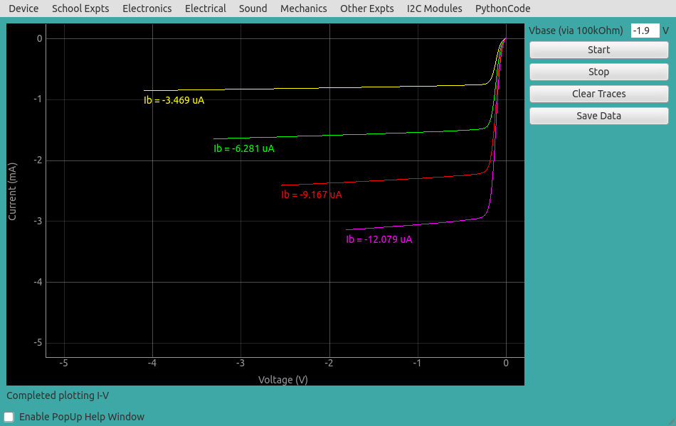
Screen shot of the output characteristics of a PNP Transistor in CE configuration