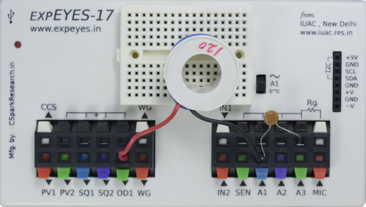
In this section, we explore the transient response of a series RLC circuit by applying voltage step and capturing the voltage variation across the capacitor. The coil used is 3000 turns of 44SWG wire.
In this section, we explore the transient response of a series RLC circuit by applying voltage step and capturing the voltage variation across the capacitor.
The coil used is 3000 turns of 44SWG wire. Its inductance is around 120 mH and the resistance is around 550 Ohms. The measured inductance value will be marked on the side of the coil, and this may be used for calculations.
The capacitance value used is 0.1 uF.
Practical difficulties
Evaluating the transient response requires triggering the oscilloscope immediately after the input voltage changes. This operation
is difficult to perform with a conventional oscilloscope. However, with the ExpEYES oscilloscope, there is an option to change the voltage
level on any of the digital outputs, and start capturing voltage signals immediately afterwards. The latency is less than a microsecond,
and this enables students to study the transient response of various circuits.
In this particular experiment, the button changes OD1 from 0 Volts to 5Volts, and records the output of the
circuit. Since it is an RLC circuit, it may oscillate, depending on the values.
In a similar fashion, the voltage can be switched from , and you can observe that the output actually drops below 0 Volts momentarily because
the magnetic field in the coil collapses.
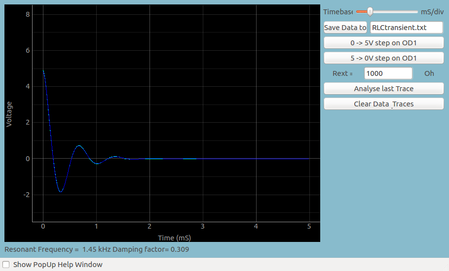
Screenshot
Analysis
You may save this data, and fit it with an appropiate mathematical function to extract the oscillation frequency, and compare it with the theoretical
frequency obtained from R, L , and C .
The fitting option is already built into the software, so you can use the calculator to estimate the frequency.
In case a series Resistor was used, its value must be supplied. Otherwise it is the resistance of the inductor which must be supplied.
 Jithin B.P.