Quick Start
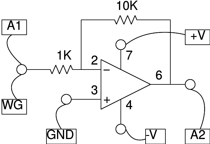
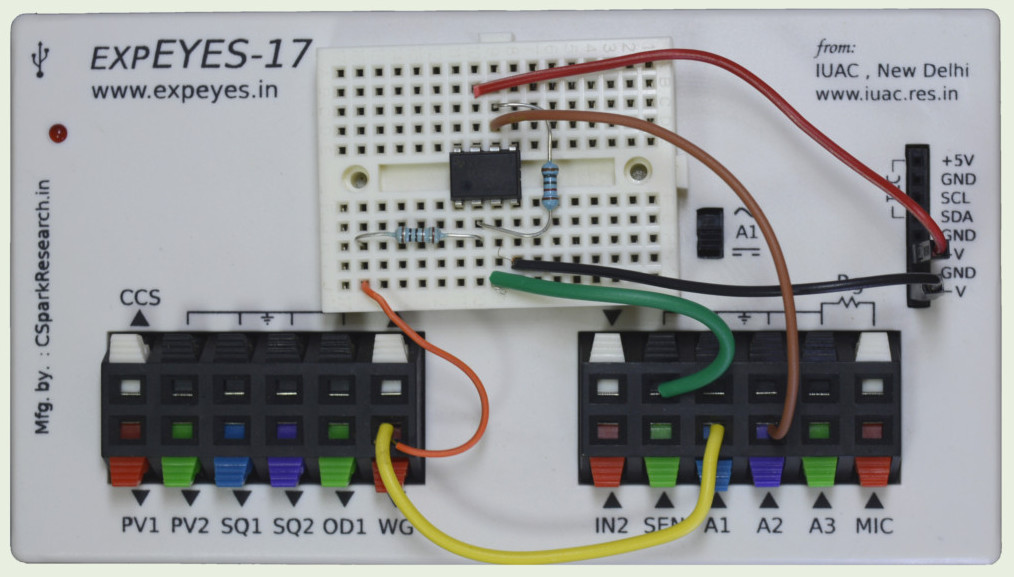
The schematic is wired as shown in the diagram below. Ri = 1k and Rf = 10k.
The WG amplitude is set to 80 mV, you may try a 1 volt input to observe the clipping of the the output, since it will exceed the op-amp supply voltage of +/- 6 volts.
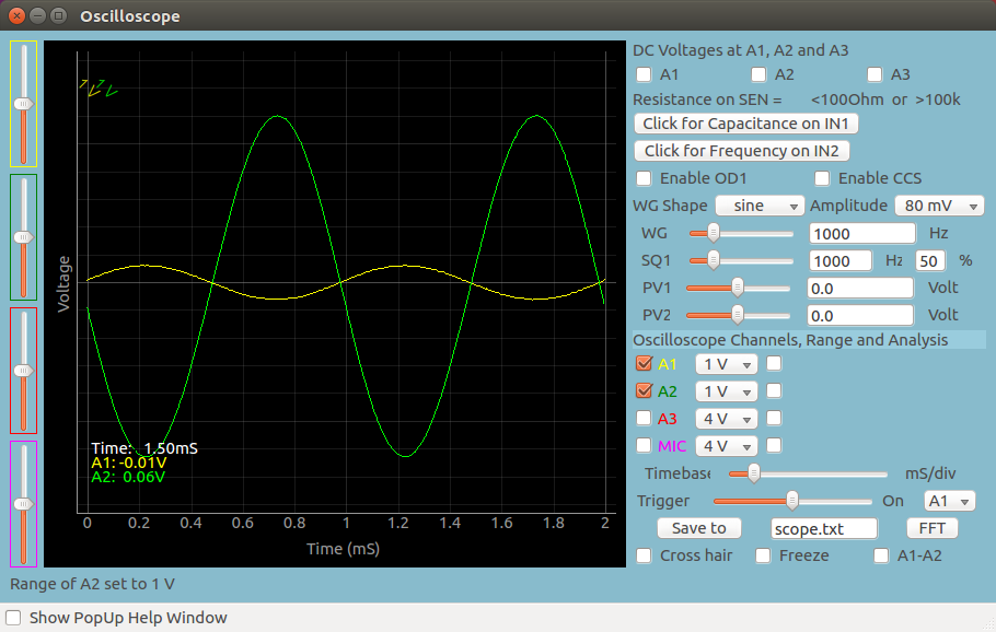
Screenshot of the UI
Screen shot of the oscilloscope program showing inputs and output of an Inverting Amplifier. Theoretical Gain is -10
Exercises
- Calculate the gain by fitting A1, and A2 by enabling the check-boxes next to them. gain = output/input
- What is the gain if Rf < Ri .
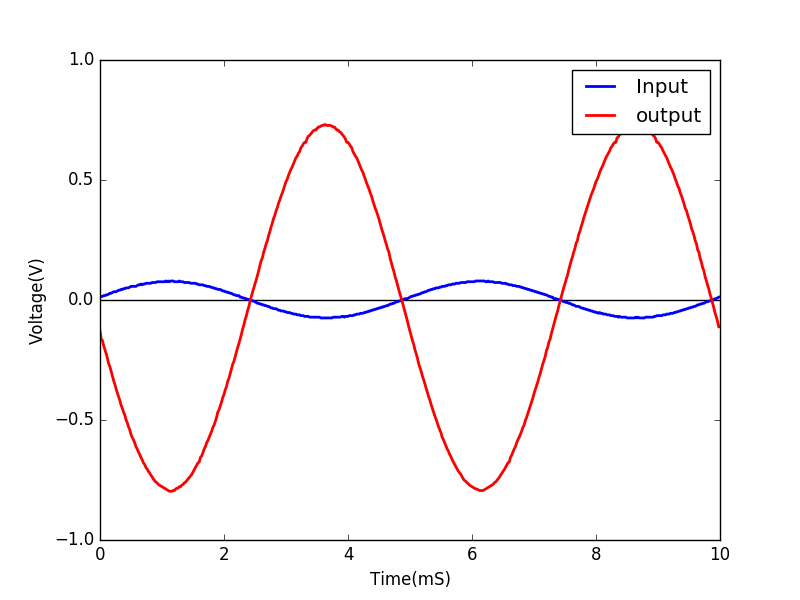
Write Python Code
This experiment can also be done by running this Python Code.
import eyes17.eyes
p = eyes17.eyes.open()

from pylab import *

p.set_sine(200)
p.set_pv1(1.35) # will clip at 1.35 + diode drop
t,v, tt,vv = p.capture2(500, 20) # captures A1 and A2

xlabel('Time(mS)') ylabel('Voltage(V)')
plot([0,10], [0,0], 'black')
ylim([-4,4])

plot(t,v,linewidth = 2, color = 'blue')
plot(tt, vv, linewidth = 2, color = 'red')
show()
 Jithin B.P.