Quick Start
In this section, we measure the amplitude and phases of voltages and currents across Resistors, Capacitors and Inductors when an AC voltage is applied. Three separate cases will be explored; Series RC circuit, RL circuit and RLC circuit. The resonance of LC circuit is explored.
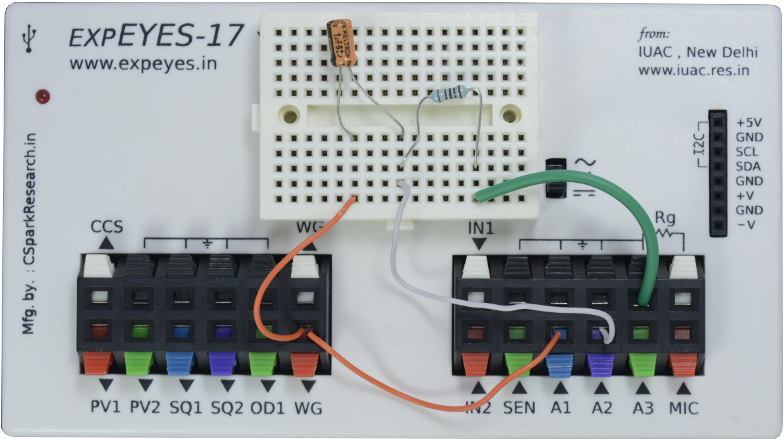
AC Voltage applied to series RC

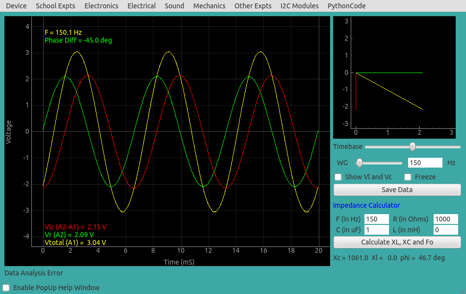
The observed waveforms are shown below. The green trace is the voltage across the resistor.
Since the current and voltage are in phase across a resistor, this trace represents the phase of current.
It can be seen that it is ahead of the red trace (voltage across C) by 90 degree, as expected.
The phase difference of voltage waveforms across the capacitor is given by atan(Zc/R).
The measured value is 45 degree and the expected value for R=1k, C = 1uF and f = 150 Hz is 46.7 degree.
To get them matching, we need to use the actual values of the resistance and capacitance in the calculations, not the nominal values printed on them.
Screenshot
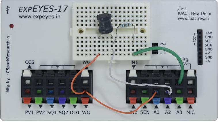
AC voltage applied to a series RL circuit

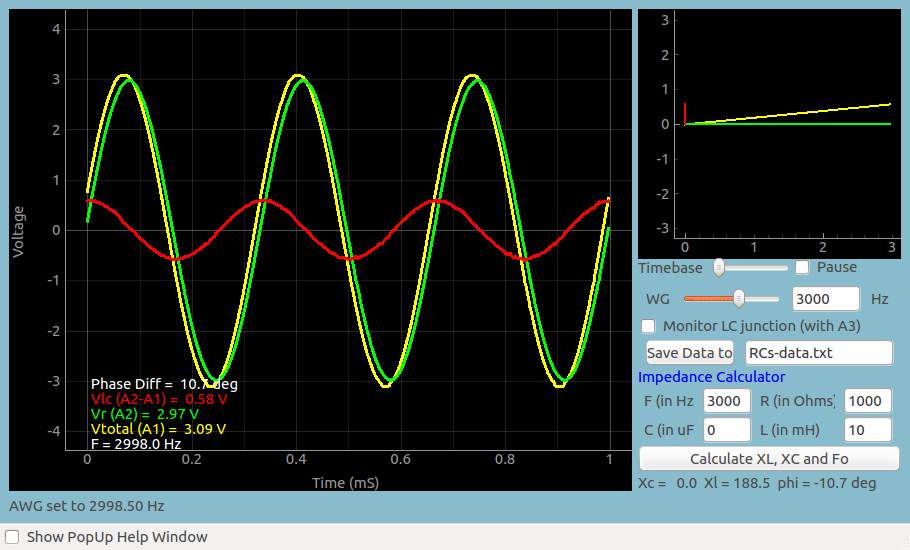
The observed waveforms are shown below. The phase difference of voltage waveforms across the capacitor is given by atan(Zl/R).
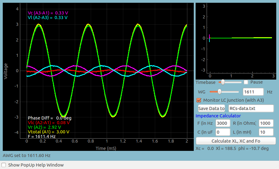
The measured value is 10.7 degree R=1k, L = 10mH and f = 3000 Hz, in agreement with calculated value.
AC voltage applied to a series RLC circuit, explore Resonance Condition

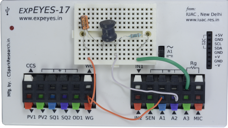
The RED trace is the voltage across LC at resonance. The individual voltage across L and C are also shown. It can be seen that the total volatge is going to zero because the voltage across each element is equal and out of phase, so they add to zero.
See Also
 Jithin B.P.