IC 555 used in an astable multi-vibrator configuration can be studied using the oscilloscope of ExpEYES. IN2 is used to precisely measure duty-cycle and frequency.
May 03, 2018
 Jithin B.P.
 Jithin B.P.
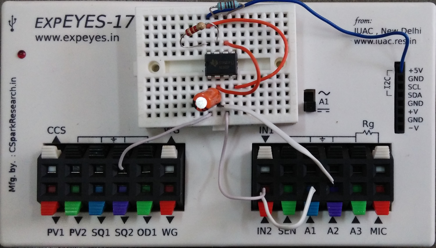
The schematic is wired as shown in the diagram below. The output of 555 is monitored on channel A1, and also connected to IN2 for frequency and duty cycle measurement. The 5 volt power can be taken from the +5V socket or from OD1 (need to enable OD1). The charging waveform may be monitored on A2. The capacitor from pin5 to ground is for noise reduction.

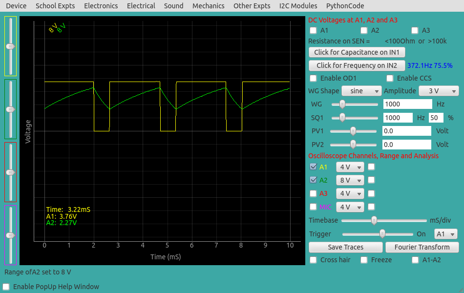
We have used R1 = 2.2K, R2 = 1K, C = 1uF . The calculated frequency and duty cycle are 343.6 Hz and 76.2%.
The measured values are shown in the figure below.
Screen shot of the oscilloscope program showing the IC555 output. The voltage across the capacitor is shown on A2.
This experiment can also be done by running this Python Code.
import eyes17.eyes
p = eyes17.eyes.open()
from pylab import *
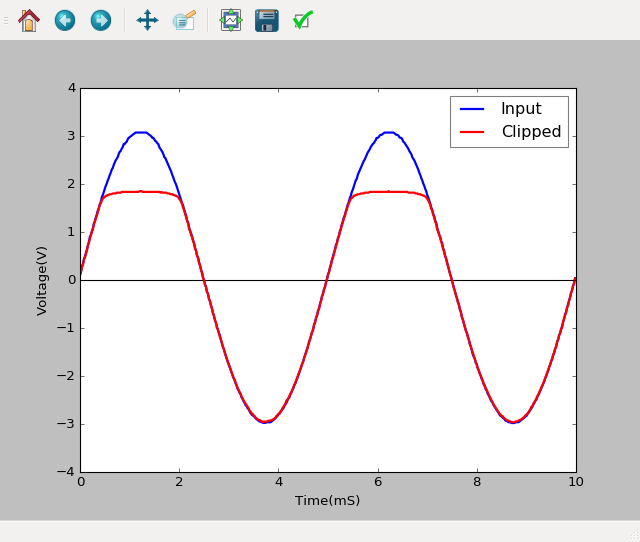
p.set_sine(200)
p.set_pv1(1.35) # will clip at 1.35 + diode drop
t,v, tt,vv = p.capture2(500, 20) # captures A1 and A2
xlabel('Time(mS)') ylabel('Voltage(V)')
plot([0,10], [0,0], 'black')
ylim([-4,4])
plot(t,v,linewidth = 2, color = 'blue')
plot(tt, vv, linewidth = 2, color = 'red')
show()