In this section, we explore the transient response of a series RC circuit by applying a voltage step and capturing the voltage variation across the capacitor.
May 02, 2019
 Jithin B.P.
Jithin B.P.
Jithin B.P.
In this section, we explore the transient response of a series RC circuit by applying voltage step and capturing the voltage variation across the capacitor.
![]()
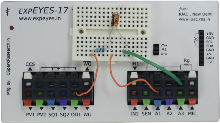
Evaluating the transient response requires triggering the oscilloscope immediately after the input voltage changes. This operation is difficult to perform with a conventional oscilloscope. However, with the ExpEYES oscilloscope, there is an option to change the voltage level on any of the digital outputs, and start capturing voltage signals immediately afterwards. The latency is less than a microsecond, and this enables students to study the transient response of various circuits.
In this particular experiment, the button changes OD1 from 0 Volts to 5Volts, and records the output of the circuit. Since it is an RC circuit, it will rapidly increase, and slow down as it approaches the maximum voltage of 5V.
In a similar fashion, the voltage can be switched from , and you can observe that the output decays exponentially.
The RC time constant can easily be calculated from this graph.
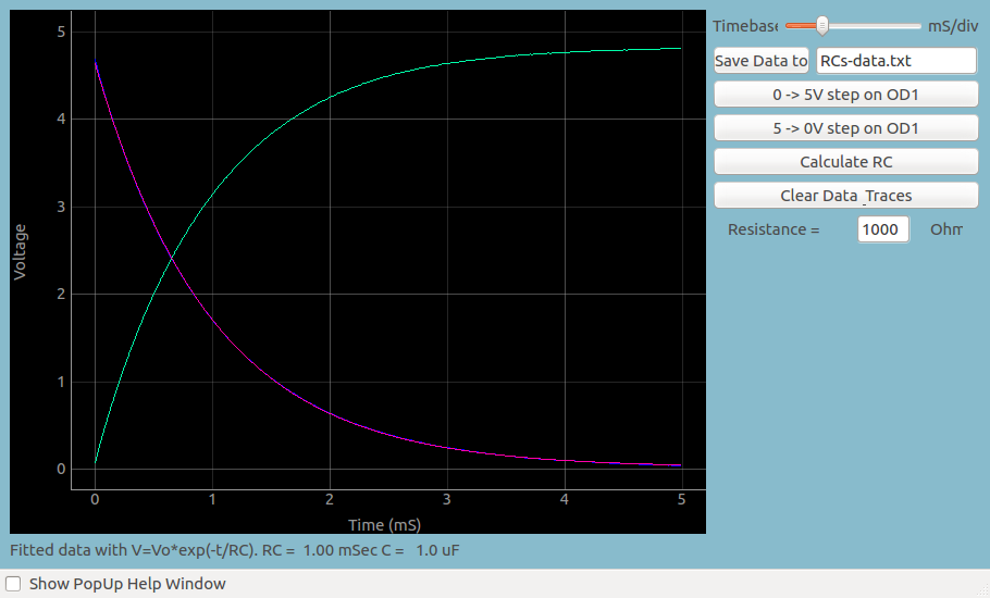
You may save this data, and fit it with an appropiate mathematical function to extract the oscillation frequency, and compare it with the theoretical frequency obtained from R and C .
The fitting option is already built into the software, so you can use the calculator to estimate the frequency.