In this section, we explore the transient response of a series RL circuit by applying a voltage step and capturing the voltage variation at the output.
May 02, 2019
 Jithin B.P.
Jithin B.P.
Jithin B.P.
In this section, we explore the transient response of a series RC circuit by applying voltage step and capturing the voltage variation across the inductor.
![]()
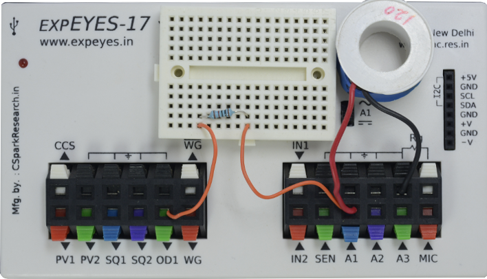
With the ExpEYES oscilloscope, there is an option to change the voltage level on any of the digital outputs, and start capturing voltage signals immediately afterwards. The latency is less than a microsecond, and this enables students to study the transient response of various circuits.
In this particular experiment, the button changes OD1 from 0 Volts to 5Volts, and records the output of the circuit. In a similar fashion, the voltage can be switched from , and you can observe the output behaviour.
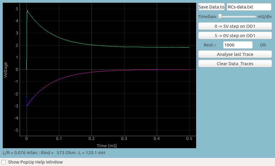
You may save this data, and fit it with an appropiate mathematical function to extract the oscillation frequency, and compare it with the theoretical frequency obtained from R and L .
It can be observed that when a 5 to 0 volt step is applied, the polarity of the voltage across the inductor is reversed and the voltage goes to negative immediately. After that the voltage reduces exponentially, driving a current through the resistor.
The resulting wave form is fitted with V = Vo x exp(R/L * t) to extract the R/L value. This also allows calculation of the value of the inductor.